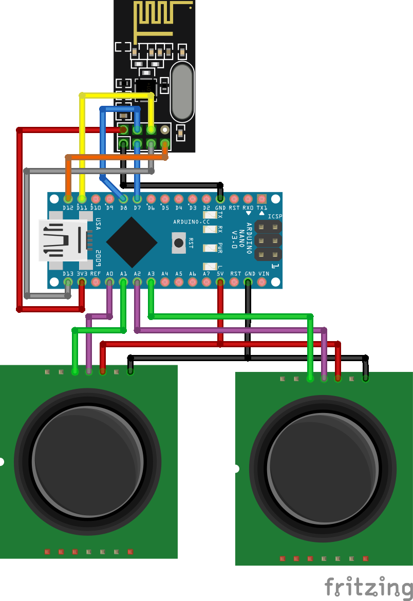
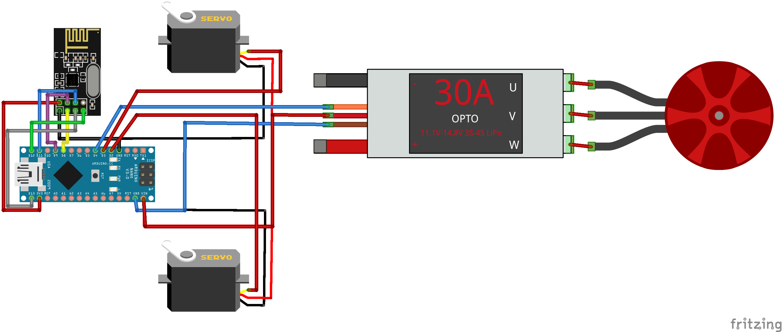
How to build an Arduino 4 Channels Wireless Transmitter Receiver
code google drive:https://drive.google.com/drive/folders/17mrTFm5VQYuR93RKNQtVAEWqd1p6sgzN?usp=sharing
| #include <SPI.h> #include <nRF24L01.h> #include <RF24.h> #include <Wire.h> RF24 radio(7, 8); // nRF24L01 (CE, CSN) const byte address[6] = "00001"; // Address // Max size of this struct is 32 bytes - NRF24L01 buffer limit struct Data_Package { byte j1X; byte j1Y; byte j2X; byte j2Y; byte pot1; byte pot2; }; Data_Package data; //Create a variable with the above structure void setup() { Serial.begin(9600); // Define the radio communication radio.begin(); radio.openWritingPipe(address); radio.setAutoAck(false); radio.setDataRate(RF24_250KBPS); radio.setPALevel(RF24_PA_LOW); // Set initial default values data.j1X = 127; // Values from 0 to 255. When Joystick is in resting position, the value is in the middle, or 127. We actually map the pot value from 0 to 1023 to 0 to 255 because that's one BYTE value data.j1Y = 127; data.j2X = 127; data.j2Y = 127; } void loop() { // Read all analog inputs and map them to one Byte value data.j1X = map(analogRead(A0),1023,0,0,255); data.j1Y = map(analogRead(A1),0,1023,0,255); data.j2X = map(analogRead(A2),0,1023,0,255); data.j2Y = map(analogRead(A3),0,1023,0,255); data.pot1 = map(analogRead(A7), 0, 1023, 0, 255); data.pot2 = map(analogRead(A6), 0, 1023, 0, 255); // Send the whole data from the structure to the receiver radio.write(&data, sizeof(Data_Package)); } |
code RCreceiver
#include <SPI.h> #include <nRF24L01.h> #include <RF24.h> #include <Servo.h> RF24 radio(8, 9); // nRF24L01 (CE, CSN) const byte address[6] = "00001"; unsigned long lastReceiveTime = 0; unsigned long currentTime = 0; #define led 9 Servo throttle; // create servo object to control the ESC Servo rudderServo; Servo elevatorServo; Servo aileron1Servo; Servo aileron2Servo; //int travel; int x1; int y1; int x2; int y2; int minRange = 85; int maxRange = 170; int throttleValue, rudderValue, elevatorValue, aileron1Value, aileron2Value, travelAdjust; // size of this struct is 32 bytes - NRF24L01 buffer limit struct Data_Package { byte j1X; byte j1Y; byte j2X; byte j2Y; byte pot1; byte pot2; }; Data_Package data; //Create a variable with the above structure void setup() { Serial.begin(9600); radio.begin(); radio.openReadingPipe(0, address); radio.setAutoAck(false); radio.setDataRate(RF24_250KBPS); radio.setPALevel(RF24_PA_MAX); radio.startListening(); // Set the module as receiver resetData(); // throttle.attach(5); // elevator1Servo.attach(3); // CH3 // elevator2Servo.attach(4); // CH4 throttle.attach(10); rudderServo.attach(4); // CH1 elevatorServo.attach(5); // CH2 aileron1Servo.attach(6); // CH3 aileron2Servo.attach(7); // CH4 pinMode(led, OUTPUT); // CH6 } void loop() { // Check whether we keep receving data, or we have a connection between the two modules currentTime = millis(); if ( currentTime - lastReceiveTime > 1000 ) { // If current time is more then 1 second since we have recived the last data, that means we have lost connection resetData(); // If connection is lost, reset the data. It prevents unwanted behavior, for eample if a drone jas a throttle up, if we lose connection it can keep flying away if we dont reset the function } // Check whether there is data to be received if (radio.available()) { radio.read(&data, sizeof(Data_Package)); // Read the whole data and store it into the 'data' structure lastReceiveTime = millis(); // At this moment we have received the data } int x1= data.j1X; int y1= data.j1Y; int x2= data.j2X; int y2= data.j2Y; // Controlling throttle - brushless motor with ESC throttleValue = constrain(data.j1X, 130, 255); // Joysticks stays in middle. So we only need values the upper values from 130 to 255 throttleValue = map(throttleValue, 130, 255, 1000, 2000); throttle.writeMicroseconds(throttleValue); // Adjusting the servos responsiveness travelAdjust = map(data.pot2, 0, 255, 0, 25); // Elevator control elevatorValue = map(data.j2X, 0, 255, (85 - travelAdjust), (35 + travelAdjust)); elevatorServo.write(elevatorValue); // Ailerons control aileron1Value = map(data.j2Y, 0, 255, (10 + travelAdjust), (80 - travelAdjust)); aileron1Servo.write(aileron1Value); aileron2Servo.write(aileron1Value); // Rudder trimming function if (data.j1Y > 127) { rudderValue = data.pot1 + (data.j1Y - 127); } if (data.j1Y < 127) { rudderValue = data.pot1 - (127 - data.j1Y); } // Rudder control rudderValue = map(rudderValue, 0, 255, (10 + travelAdjust), (90 - travelAdjust)); rudderServo.write(rudderValue); // Monitor the battery voltage int sensorValue = analogRead(A3); float voltage = sensorValue * (5.00 / 1023.00) * 3; // Convert the reading values from 5v to suitable 12V i // If voltage is below 11V turn on the LED if (voltage < 11) { digitalWrite(led, HIGH); } else { digitalWrite(led, LOW); } } void resetData() { data.j1X = 127; data.j1Y = 127; data.j2X = 127; data.j2Y = 127; data.pot1 = 1; data.pot2 = 1; } |
Powered by Froala Editor
;
